40 Results
View results:
Sort by:

The goal of using the RFEM 6 and Blender with the Bullet Constraints Builder add-on is to obtain a graphical representation of the collapse of a model based on real data of physical properties. RFEM 6 serves as the source of geometry and data for the simulation. This is another example of why it is important to maintain our programs as so-called BIM Open, in order to achieve collaboration across software domains.

The size of the computational domain (wind tunnel size) is an important aspect of wind simulation that has a significant impact on the accuracy as well as the cost of CFD simulations.

Windbreak structures are special types of fabric structures which protect the environment from harmful chemical particles, abate wind erosion, and help to maintain valuable sources. RFEM and RWIND are used for wind-structure analysis as one-way fluid-structure interaction (FSI).
This article demonstrates how to structural design windbreak structures using RFEM and RWIND.

This technical article presents some basics for using the Torsional Warping add-on (7 DOF). It is fully integrated into the main program and allows you to consider the cross-section warping when calculating member elements. In combination with the Stability Analysis and Steel Design add-ons, it is possible to perform the lateral-torsional buckling design with internal forces according to the second-order analysis, taking imperfections into account.

The new generation of RFEM software is an intuitive, powerful, and easy-to-handle 3D FEA program that meets all the latest demands in modeling, calculation, and structural design. The modern design concept, as well as the introduction of new features, make the program even more innovative and user-friendly. The main differences between RFEM 6 and its previous version, RFEM 5, are discussed in the following text.

For designing glass in the RF‑GLASS add‑on module, you can use one of two calculation methods: a 2D or a 3D calculation. The main difference between these design options is the automatic modeling of the layers in a temporary model. In a 2D calculation, each layer is generated as a surface element (plate theory); in a 3D calculation, it is generated as a solid. Depending on the selected layer composition, you can either select an option or find it preselected by the program.

The joint type "Main member only" in RF‑/JOINTS Timber - Steel to Timber can also be applied for more than one connected member.

When calculating foundations according to EC 7 or EC 2, different foundation types or sizes are usually used in one object. However, boundary conditions like the soil parameters, the materials for foundations, concrete covers, and the load combinations selected for design remain the same for all foundations, as a rule.
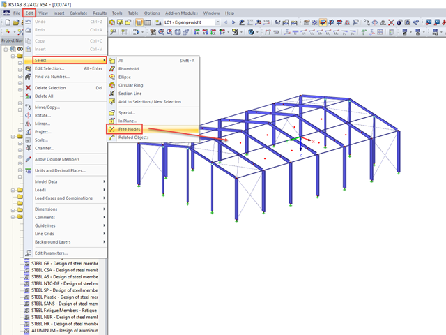
When you finish modeling a structure, it can often happen that some unused nodes remain in the model.

The most common causes of unstable models are failing member nonlinearities such as tension members. As the simplest example, there is a frame with supports on the column footing and moment hinges on the column head. This unstable system is stabilized by a cross bracing of tension members. In the case of load combinations with horizontal loads, the system remains stable. However, if it is loaded vertically, both tension members fail and the system becomes unstable, which causes a calculation error. You can avoid such an error by selecting the exceptional handling of failing members under "Calculate" → "Calculation Parameters" → "Global Calculation Parameters".

In EN 1993-1-1, the General Method was introduced as a design format for stability analyses that can be applied to planar systems with arbitrary boundary conditions and variable structural height. The design checks can be performed for loading in the main load-bearing plane and simultaneous compression. The stability cases of lateral-torsional buckling and flexural buckling are analyzed from the main supporting plane; that is, about the weak component axis. Therefore, the issue often arises as to how to design, in this context, flexural buckling in the main load-bearing plane.

When using the RF‑GLASS add‑on module, you can define just the geometry in the main program, as well as the load situation of the structural component to be designed. The respective support conditions and all further design-relevant definitions (for example, the layer structure and support conditions), can be further specified in RF‑GLASS.

In the case of open cross-sections, the torsional load is removed mainly via secondary torsion, since the St. Venant torsional stiffness is low compared to the warping stiffness. Therefore, warping stiffeners in the cross-section are particularly interesting for the lateral-torsional buckling analysis, as they can significantly reduce the rotation. For this, end plates or welded stiffeners and sections are suitable.
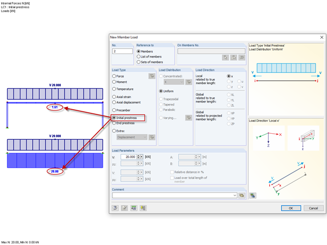
Until now, the prestress load type had always been an initial prestress in Dlubal Software programs. The defined load magnitude was applied and, depending on the stiffness of the surrounding system, prestress remained more or less as an axial force in the cable.
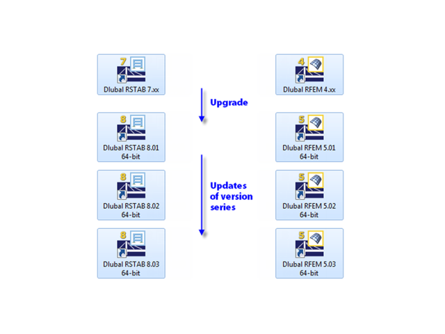
When updating within a version series (for example, RFEM 5.01.01 to 5.01.02), the old program files are removed and replaced by new ones. The project data, of course, remain unchanged. When updating to the next version series (for example, RFEM 5.02.01), the new version is installed in parallel. The program files are located in different directories, so the previous version is still available.

Steel-fiber-reinforced concrete is mainly used nowadays for industrial floors or hall floors, foundation plates with low loads, basement walls, and basement floors. Since the publication in 2010 of the first guideline about steel-fiber-reinforced concrete by the German Committee for Reinforced Concrete (DAfStb), a structural engineer can use standards for the design of the steel fiber-reinforced concrete composite material, which makes the use of fiber-reinforced concrete increasingly popular in construction. This article describes the nonlinear calculation of a foundation plate made of steel fiber-reinforced concrete in the ultimate limit state with the FEA software RFEM.

Determining the Material Properties of Steel-Fiber-Reinforced Concrete and Their Application in RFEM
Steel-fiber-reinforced concrete is mainly used nowadays for industrial floors or hall floors, foundation plates with low loads, basement walls, and basement floors. Since the publication in 2010 of the first guideline about steel-fiber-reinforced concrete by the German Committee for Reinforced Concrete (DAfStb), a structural engineer can use standards for the design of the steel fiber-reinforced concrete composite material, which makes the use of fiber-reinforced concrete increasingly popular in construction. This article explains the individual material parameters of steel-fiber-reinforced concrete and how to deal with these material parameters in the FEM program RFEM.

Wind blowing parallel to the surfaces of a structure can generate friction forces on these surfaces. This effect is important mainly for very large structures.
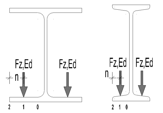
For suspension cranes, the bottom chord of the runway girder is subjected to local flange bending due to the wheel loads in addition to the main load-bearing capacity. The bottom chord behaves like a slab due to these local bending stresses, and has a biaxial stress condition [1].
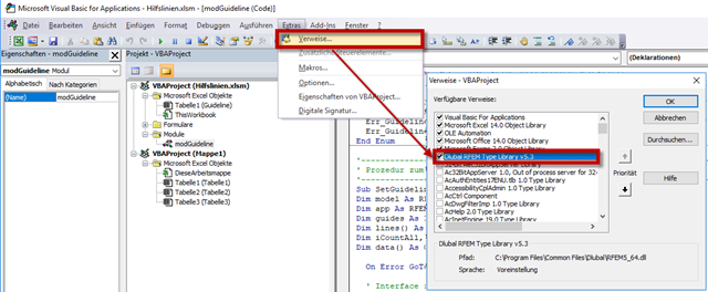
RF-COM/RS-COM is a programmable interface that allows the user to expand the main programs RFEM and RSTAB with customized input macros or post‑processing programs. A tool to copy and move selected guidelines in RFEM will be developed in this article. It is also possible to copy or move the guidelines to another work plane. VBA in Excel will be used as the programming environment.
RF-/JOINTS Timber – Timber to Timber allows you to design main-connected beam joints. This article explains the determination of forces in screws of a beam connected to a torsionally rigid main beam.

Wind is the only climatic load acting on every type of structure in every country in the world, unlike snow. The wind speed depends on the geographic location of the building. Currently, this is one of the main reasons for the necessity of regional division (wind zone) and consideration of the altitude stipulated within the official standards; the variation of the dynamic pressures according to the height above the ground for a "normal" site deprived of masking effect should be taken into account as well.
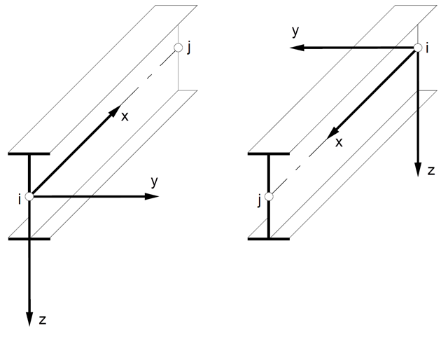
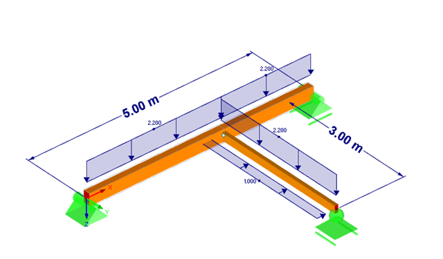
In spatial structures, the member position plays an important role in terms of determining internal forces. The orientation of member axes can be defined either by a global cross-section rotation angle, or by a specific member rotation angle. These two angles are added to determine the position of the main axes of a member in a 3D model.
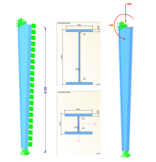
The following structure is covered as Example IV.10 in [1] "Comment on Eurocode 3". For a support with a linearly varying cross‑section, a sufficient ultimate limit state design (cross‑section check and stability analysis) is to be performed. Due to the unequal structural component, it is necessary to perform the stability analysis (from the main support direction) using the method according to Section 6.3.4, or alternatively, according to the second‑order analysis.

Composite beams in a three-dimensional analysis are usually connected with orthotropic plates. In that case, the longitudinal direction of the plate stiffness is defined by a main beam and the transverse direction by an orthotropic plate. The stiffness of the plate in the longitudinal direction is set almost to zero. This article explains the determination of stiffnesses in the orthotropic plate.
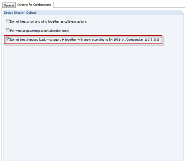
In the H - Roofs category, imposed loads have to be applied. These are usually the technician loads for construction and maintenance. Since there is no maintenance for snow, category H must not include both snow and imposed loads together. You can consider thi in the options for automatic combinations.
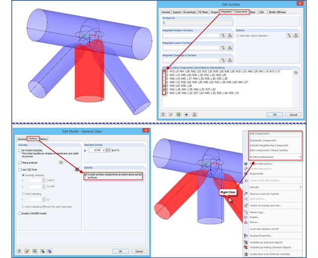
If intersections created in RFEM 4 are opened in an RFEM 5 file, the file management of intersections remains in the old format for compatibility reasons. Thus, the individual partial surfaces of the intersection can be activated or deactivated using only the "Integrated/Components" tab, all partial surfaces can only have the same thickness, and it is impossible to use the separate FE mesh refinement for the individual surface components.
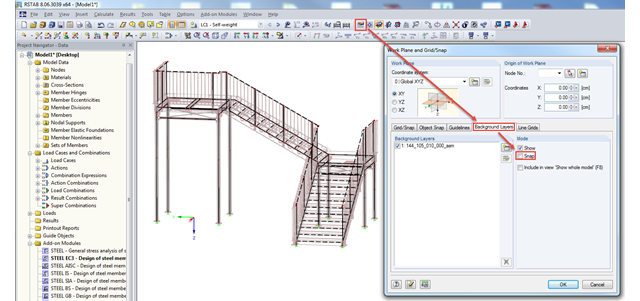
In RFEM and RSTAB, you can import background layers from a DXF file. If the main nodes of the model have already been set, it can be useful to deactivate the snap mode of the background layer.
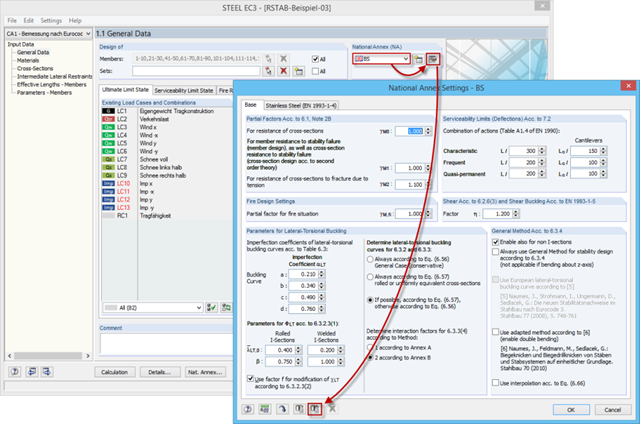
If you want to design structural components in an RFEM or RSTAB add‑on module, several National Annexes are available in some add‑on modules. In the case of structures that are to be analyzed mainly according to a specific National Annex, the add‑on modules provide the option to set a default value. Thus, it is unnecessary to select the NA again for each new model.
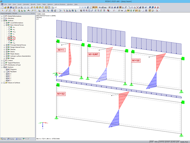
When analyzing structural components of reinforced concrete structures, it is often necessary to design deep beams. These are mainly used for window and door lintels, upstand and downstand beams, the connection between split-level slabs, and frame systems. If they are displayed as surfaces in RFEM, the evaluation of reinforcement results requires further steps.